NZR
R-project

One thing about Ogre Cameras that is different from what you may expect is that you should only be using one Camera at a time (for now). That is, we do not create a Camera for viewing one portion of a scene, a second camera for viewing another portion of the scene and then enabling or disabling cameras based on what portion of the scene we want to display. Instead the way to accomplish this is to create SceneNodes which act as "camera holders". These SceneNodes simply sit in the scene and point at what the Camera might want to look at. When it is time to display a portion of the Scene, the Camera simply attaches itself to the appropriate SceneNode.
After the SDK is installed, add "include" and "bin" directory of the SDK to the Visual Studio's VC++ Directories.
For each project, add "CEGUIBase.lib", "ode.lib", "OgreGUIRenderer.lib", "OgreMain.lib", "OIS.lib" and "ReferenceAppLayer_d.lib" to project's Link menu and Additional Dependencies. (Add all or add only the one you will use in your code.) Moreover, for the first 5 lib files, there is a version for debug: "CEGUIBase_d.lib", "OgreGUIRenderer_d.lib", "OgreMain_d.lib", "OIS_d.lib".
If you try to launch your freshly built application but the program complains of missing DLLs or configuration files (*.cfg), then you probably did not copy them over from the OgreSDK folder. In Visual Studios, when you build your application in release mode, it puts the release executable in the [ProjectFolder]\bin\release folder, and the debug executable in the [ProjectFolder]\bin\debug folder. You must copy all the ".dll" and ".cfg" files over from the OgreSDK into the appropriate folders. That is, copy the files from [OgreSDK]\bin\release to [ProjectFolder]\bin\release and [OgreSDK]\bin\debug to [ProjectFolder]\bin\debug. You will also need to edit the resources.cfg file to point at the correct paths. See the next section for more information on this.
Also something in the "Resources.cfg" configuration file should be changed. However, I just copied the media folder to my project folder.
If you are using Visual Studio or Visual C++ to create the application and are having trouble launching it from the environment, the problem is most likely due to the debugger settings. If you press the play button (or go to the Start Debugging menu item) and you get an exception saying that a configuration file (*.cfg) cannot be found, then the Working Directory has probably not been set.
The exact instructions for fixing this will vary based on whichversion of Visual C++ you are using, so I cannot give you a direct walk through, but the basic steps should be the same. Right click on your project in the solution explorer (not the solution itself) and go to properties. Somewhere in the configuration properties should be options for "Debugging". In the debugging options there should be a field for "Working Directory". This should be set to the location that the executable file for your project is being placed.
If you are having trouble figuring out what to put there, try to mimic the "Command" field which should also be in the debugging options. For example, in Visual C++ 2003, the "Command" field should be something similar to "..\..\bin\$(ConfigurationName)\$(TargetFileName)". For the Working Directory, we need to remove the portion of the command which is the target file name (the executable). In this case, the working directory would be "..\..\bin\$(ConfigurationName)". The exact string you have to put there may vary based on your version of Visual C++ and on your build environment, so be sure to check what the Command field is before doing this. Be sure to change the Working Directory for both the Release and Debug configuration.
In Visual C++ 2005 it will probably be something different entirely. I've found the "..\..\bin\$(ConfigurationName)" directory a good thing to try first, if it still does not work you may have to play with it some, or consult some help from the Ogre forums.
The reason we have to do this is that Ogre expects certain files to be in the same directory as the executable, and without setting the working directory to be a directory with these files in it.
SceneNodes keep track of location and orientation for all of the objects attached to it. When you create an Entity, it is not rendered in the scene until you attach it to a SceneNode.In addition a SceneNode is not an object that is displayed on the screen. Only when you create a SceneNode and attach an Entity (or other object) to it is something actually displayed on the screen.
One major concept to note about SceneNodes is that a SceneNode's position is always relative to its parent SceneNode, and each SceneManager contains a root node to which all other SceneNodes are attached.
One of the most crucial pieces in the game is the media used to represent the players. This must allow for enough customization for the players to feel that they are in a living world, where they themselves are unique, as well as all of the other character. Therefore we need to have a common standard for all humanoid characters, so that they will all be able to represent the world in a correct way no matter what client they're used in.
An initial layout of the humanoid characters. The layout should be closely followed for female characters.

![]()
The clothes parts needs to be synced with the body model. As an example, a long sleeved shirt will cover most of the arms, allowing the client to hide the "shoulder" and "elbow" parts (thus saving render ops), whereas a shirt sleeved shirt would require that either the "elbow" or also the "shoulder" part was visible.
The armour should mostly be a suppliment to the clothing, i.e. it should be possible to wear a "shin guard" and a "long pants" at the same time. Some armour parts however takes precedence, for example when wearing a chain mail legging, all other pants that might be worn should automatically be hidden. An overview of the armour layout can be seen in the image to the left.

![]()
The animations should correspond directly to actions in mason, in addition to the standard movement animations. The following is a compilation of the current status of the animations available for the humanoid character in Ember, and how they map against the server side actions.
Models
Animation name
Description
Ember name
Server actions
Status
Idle
The character is idle, breathes and perhaps shifts position, cracks the knuckles etc.. This would preferably be a couple of different animations that can be randomly played, to not make it too apparent that they're looping.
humanoid.skeleton: wf_humanoid-idle_*
Idle
Walk forwards
Simple forward walking animation
humanoid.skeleton: wf_humanoid_walk_Clip
Move forwards
Walk backwards
Simple backwards walking animation
Move backwards
Run forwards
Simple forward running animation
humanoid.skeleton: wf_humanoid_walk_Clip
Move forwards with greater speed
Sidestep
Simple side stepping walking animation
Move to the side
Swim
The character swims. For now we'll use the same animation for both idle and movement.
The character is placed in water
Pickup
The character picks something from the ground. The same animation can be used when the character drops something.
humanoid.skeleton: wf_humanoid-pick-up_Clip
Action: pickup, drop
General fidgeting
A general animation that can be used whenever there's no other animation to use for an action
humanoid.skeleton: wf_humanoid-fletching_Clip
Generic action
Chop
The character chops down a tree.
Action: chop
Punch
The character makes an offensive punch
humanoid.skeleton: wf_humanoid-offense_punch_Clip
Action: attack
Swing a sword
The character makes an offensive swing with a sword
Action: attack
Defend
The character defends against an offensive action
Action: defend
Eat
The character eats
Action: eat
Collapse
After being defeated in combat or starving to death, the character should collapse and end up in a collapsed state on the ground.
Action: collapse
Rise
After collapsing in combat, the character gets up again.
Action: ?
Dig
The character digs in the ground.
Action: dig
Delve
The character uses a pickaxe to delve.
Action: delve
Sow
The character uses a trowel to sow a seed in the ground.
Action: sow
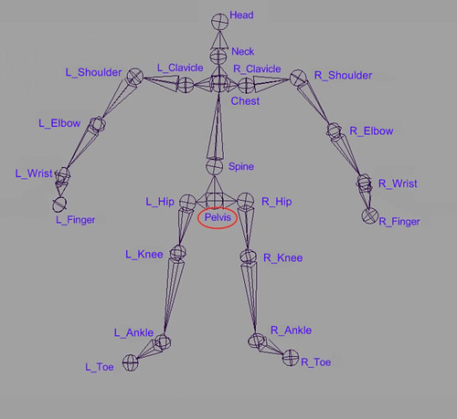
To animate the humanoid character, a well defined skeleton is used. Following is the skeleton we studied and used in our work.
The skeleton(using maya joint):
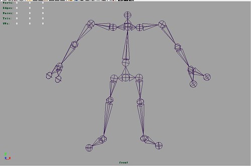
The hierarchy of this skeleton is:
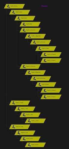
The hierarchy also can be seen from following selections in Maya:
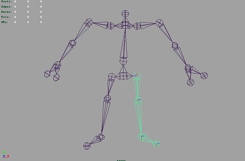
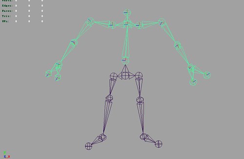
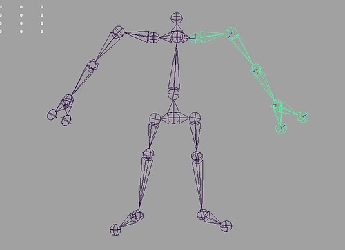
The annotated reference skeleton model is:
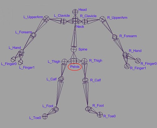
The one we use is slightly different in the neck area:
This page lists "small" pieces of geometric software available on the Internet. Most of the software is available free of charge. Unless otherwise specified, C or C++ source code is available for all programs. Software libraries and collections and programs that can be run interactively over the web are listed on separate web pages.
Caveat Surfor! I can't make any claims about the usefulness or quality of the programs listed here. I don't have the time or equipment to try them all. If you have experience with any of these programs, either positive or negative, please tell me about it.
The programs on this page are divided into several categories, some of which are divided into further sub-categories. (Eventually, each category will get its own separate web page.) Each program is listed only once, but I've provided cross-links between overlapping categories, and I've tried to arrange similar categories near each other.
Items marked ![[NEW!]](http://compgeom.cs.uiuc.edu/%7Ejeffe/compgeom/pix/new.gif) have been recently added or modified.
have been recently added or modified.
A much smaller version of the same algorithm, written in C by Alexy Nitikin and Michael Leonov, also handles polygons with holes. [New URL]From: http://compgeom.cs.uiuc.edu/~jeffe/compgeom/code.html#mesh
Unity - A good commercial engine. Development only supports MacOS.
Blink 3D
http://www.pelicancrossing.com/index.htm
Commercial. Provides a free version.
Emma3D
http://emma3d.sourceforge.net/
Open-source.
Given points P0 and P1, a linear Bézier curve is simply a straight line between those two points. The curve is given by
![\mathbf{B}(t)=\mathbf{P}_0 + t(\mathbf{P}_1-\mathbf{P}_0)=(1-t)\mathbf{P}_0 + t\mathbf{P}_1 \mbox{ , } t \in [0,1]](http://upload.wikimedia.org/math/a/d/9/ad90a6fecd5324dc32f75f0b19c2d684.png)
and is equivalent to linear interpolation.
A quadratic Bézier curve is the path traced by the function B(t), given points P0, P1, and P2,
![\mathbf{B}(t) = (1 - t)^{2}\mathbf{P}_0 + 2(1 - t)t\mathbf{P}_1 + t^{2}\mathbf{P}_2 \mbox{ , } t \in [0,1].](http://upload.wikimedia.org/math/2/d/5/2d5e5d58562d8ec2c35f16df98d2b974.png)
A quadratic Bézier curve is also a parabolic segment.
TrueType fonts use Bézier splines composed of quadratic Bézier curves.
Four points P0, P1, P2 and P3 in the plane or in three-dimensional space define a cubic Bézier curve. The curve starts at P0 going toward P1 and arrives at P3 coming from the direction of P2. Usually, it will not pass through P1 or P2; these points are only there to provide directional information. The distance between P0 and P1 determines "how long" the curve moves into direction P2 before turning towards P3.
The parametric form of the curve is:
![\mathbf{B}(t)=(1-t)^3\mathbf{P}_0+3(1-t)^2t\mathbf{P}_1+3(1-t)t^2\mathbf{P}_2+t^3\mathbf{P}_3 \mbox{ , } t \in [0,1].](http://upload.wikimedia.org/math/5/e/3/5e32b674a98a9f70e492851f9ad92b61.png)
Modern imaging systems like PostScript, Asymptote and Metafont use Bézier splines composed of cubic Bézier curves for drawing curved shapes.
![Animation of a linear Bézier curve, t in [0,1]](http://en.wikipedia.org/wiki/File:Bezier_1_big.gif)
Animation of a linear Bézier curve, t in [0,1]
The t in the function for a linear Bézier curve can be thought of as describing how farB(t) is from P0 to P1. For example when t=0.25, B(t) is one quarter of the way from pointP0 to P1. As t varies from 0 to 1, B(t) describes a curved line from P0 to P1.
For quadratic Bézier curves one can construct intermediate points Q0 and Q1 such that as t varies from 0 to 1:

![Animation of a quadratic Bézier curve, t in [0,1]](http://en.wikipedia.org/wiki/File:Bezier_2_big.gif)
Construction of a quadratic Bézier curve
Animation of a quadratic Bézier curve, t in [0,1]
For higher-order curves one needs correspondingly more intermediate points. For cubic curves one can construct intermediate points Q0, Q1 & Q2 that describe linear Bézier curves, and points R0 & R1 that describe quadratic Bézier curves:

![Animation of a cubic Bézier curve, t in [0,1]](http://en.wikipedia.org/wiki/File:Bezier_3_big.gif)
Construction of a cubic Bézier curve
Animation of a cubic Bézier curve, t in [0,1]
For fourth-order curves one can construct intermediate points Q0, Q1, Q2 & Q3 that describe linear Bézier curves, points R0, R1 &R2 that describe quadratic Bézier curves, and points S0 & S1 that describe cubic Bézier curves:

![Animation of a quartic Bézier curve, t in [0,1]](http://en.wikipedia.org/wiki/File:Bezier_4_big.gif)
Construction of a quartic Bézier curve
Animation of a quartic Bézier curve, t in [0,1]
(See also a construction of a fifth-order Bezier curve.)
http://graphics.stanford.edu/~levoy/ (a pioneer)
http://physbam.stanford.edu/~fedkiw/ ( a large number of publication, simulation, G number of researchers)
http://people.csail.mit.edu/jovan/ ( Jovan Popovic)
http://graphics.stanford.edu/~hanrahan/ (rendering)
http://www.cs.cornell.edu/~srm/research.html ( he is more working on modelling)
http://www.cs.cornell.edu/~djames/research/index.html (his research has many about deformation processing)
http://www.cs.cornell.edu/~kb/ (her recently paper has some relations with perception)
http://www.cs.cornell.edu/~snavely/
MIT:
http://groups.csail.mit.edu/graphics/research.html
Utah:
http://www.cs.utah.edu/research/areas/graphics/
http://www.cs.utah.edu/research/areas/percept/perception.html
Cornell:
http://www.graphics.cornell.edu/publications.html
Stanford:
Brown:
